01
Flight physics coupled payload, endurance and safety
Mass, rotor disc area and pack energy determine hover power and endurance together. Adding a sensor or recovery system changes the same equation the aircraft depends on to remain airborne.
Product design case study
RD-A7
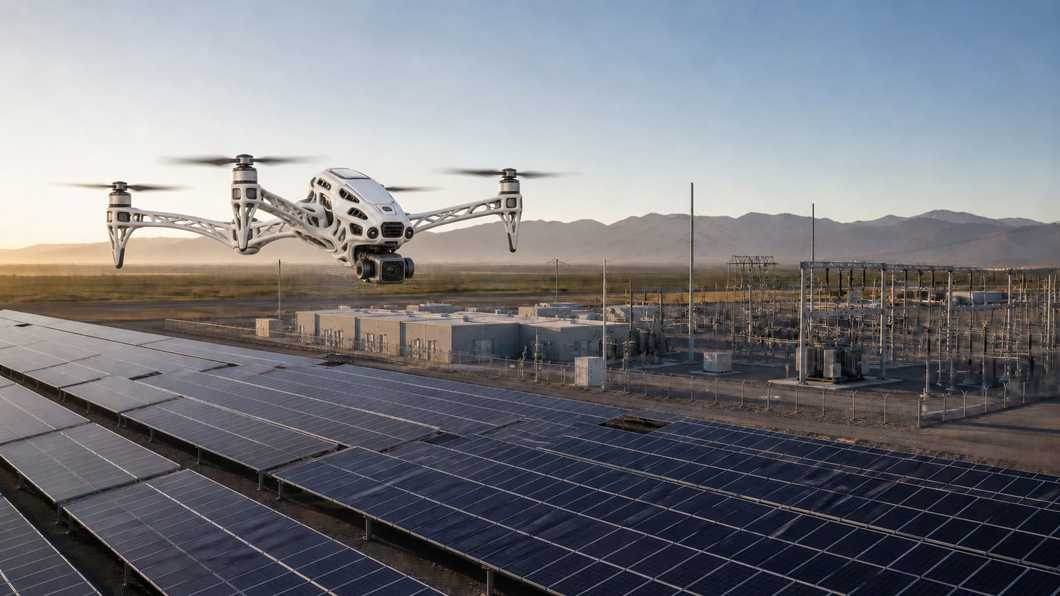
RD-A7 is Root Digit’s four-rotor aerial inspection platform for repeatable surveys of fixed assets. Its airframe, positioning, sensing, onboard inference and safety controls are designed from the defect that must be measured and the frequency at which it must be checked.
The problem
Most aerial inspection produces photographs. A useful inspection programme needs evidence that can be compared across time: the same feature at a known position, resolution and viewing geometry, with enough sensor fidelity to distinguish change from capture error.
The design problem was therefore larger than building a stable drone. The platform had to repeat survey lines, hold the required standoff, preserve georeferencing through degraded navigation conditions and return visual and radiometric data whose measurement limits were known before flight.
Why it was difficult
These operating and governance conditions determined what a credible solution had to achieve.
01
Mass, rotor disc area and pack energy determine hover power and endurance together. Adding a sensor or recovery system changes the same equation the aircraft depends on to remain airborne.
02
Metre-level standalone GNSS cannot place a later survey over an earlier one. Position, heading and time therefore needed a shared precision architecture with a post-processed fallback.
03
Altitude, focal length and pixel pitch determine ground sample distance. A faster flight at greater standoff is not useful if the smallest relevant defect disappears below the sensor’s reliable detection limit.
04
Low texture, dust, glare, smoke, GNSS multipath and link loss can occur together. Redundancy had to combine sensing principles that fail differently and preserve a recoverable state.
The solution
Root Digit designed RD-A7 as a repeatable measurement platform: a 4.2 kg four-rotor aircraft with integrated multi-band GNSS, network RTK, dual-antenna heading, radar terrain following and visual-inertial navigation for degraded positioning conditions.
A mechanical-shutter visual sensor and radiometric thermal channel provide comparable inspection evidence, while onboard inference can identify candidate defects during flight. Triple inertial sensing, independent recovery, encrypted storage and signed firmware keep navigation, evidence and platform control within one governed design.
How we did it
The workstreams below show how the solution was designed, built and controlled.
01
Hover power was derived from take-off mass and total disc area, then reconciled with drivetrain loss, usable pack energy, endurance and payload. The same approach sized the parachute recovery target rather than treating it as an accessory.
02
Integrated multi-band GNSS accepts network RTK corrections over LTE, logs raw observables for PPK fallback and uses a 0.55 m dual-antenna baseline to stabilise heading for georeferencing.
03
Radar altitude closes the loop against the surface below the aircraft, while visual-inertial odometry supports motion estimation when GNSS is obstructed or corrupted by multipath.
04
The imaging design works backward from the smallest defect. Ground sample distance, standoff and flight speed define mission limits, while radiometric thermal data preserves temperature values for comparison rather than only a false-colour image.
05
Triple inertial sensing with median voting, dual barometers, complementary stereo and radar obstacle sensing, a ballistic recovery system and secure device identity reduce single-point failures across flight and data handling.
System design
01
Required defect size and inspection frequency determine sensor, standoff, route spacing and mission cadence before a flight plan is accepted.
02
RTK, dual-antenna heading, visual-inertial odometry and radar altitude support the flight state; independent limits and recovery controls bound what the autonomy system may do.
03
Georeferenced visual and radiometric observations are retained with position, time and mission context so later surveys can be compared against the same asset features.
Outcomes and evidence
These figures are the current coupled engineering specification for the platform; they are not presented as customer-deployment outcomes.
Current specification with RTK fixed.
Derived from the coupled mass, disc-area and pack design.
At 3 m standoff under the specified visual geometry.
For the primary or optional inspection sensor configuration.
Product design conclusion
RD-A7 is designed from the inspection decision backward: define what must be detected, preserve the geometry needed to detect it again, and govern the flight and evidence chain so two surveys can be compared with technical confidence.
Start a conversation
We use cookies to enhance your browsing experience, serve personalized content, and analyze our traffic. By clicking "Accept All", you consent to our use of cookies. You can also choose "Necessary Only" to limit cookies to essential website functions only. Learn more